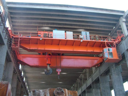
Ladle cranes are critical equipment in metallurgical production, undertaking heavy-load lifting, material handling, and process coordination tasks. Their safe and stable operation directly impacts production efficiency, personnel safety, and equipment service life. This article is divided into four core sections. It first elaborates on the inspection methods for ladle cranes, then summarizes common issues, and finally proposes specific inspection priorities and precautions—aiming to ensure the safe and stable operation of ladle overhead cranes and meet the needs of metallurgical production.
To accurately assess the performance and safety status of ladle cranes, multiple professional inspection methods are widely used in the crane industry. The most common ones include the level gauge method, total station method, and tensioned wire method, each with unique application scenarios and operational characteristics.
The level gauge method is one of the most frequently used techniques in ladle crane inspection due to its simplicity, cost-effectiveness, and reliability. It mainly includes two operational modes: the high-altitude measurement method and the suspended wire method.
This method requires placing a level gauge correctly in the metallurgical production area (ensuring it is stable and level). Next, a measuring rod is positioned on the track pressing plate, with a slight offset from the track center to avoid interference from track edges. The level gauge is then used to measure parameters such as track levelness, beam deflection, and height differences between key points. All data are recorded accurately for subsequent analysis to identify deviations in the crane structure or track system.
In this approach, a steel wire rope (with a measuring rod attached) is suspended below the crane’s main girder. The level gauge is set up on a horizontal ground surface (away from vibration sources) to measure the vertical distance between the suspended wire and the main girder’s top surface at multiple points. By comparing and analyzing the measured data, potential issues such as main girder deformation, uneven load distribution, or track misalignment within the crane system can be detected early.
The total station method is a modern, high-precision inspection technique that significantly improves efficiency and accuracy compared to traditional methods. It excels in measuring verticality and height differences of crane structures, making it ideal for comprehensive parameter testing.
Key advantages and operational steps:
The tensioned wire method is specifically designed to measure the camber of the main girder—a critical indicator of the crane’s load-bearing capacity and structural integrity.
Operational procedures:
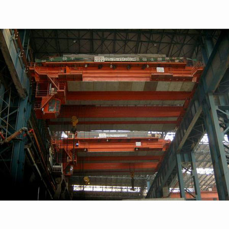
During long-term operation in harsh metallurgical environments (high temperature, dust, vibration, and heavy loads), ladle overhead cranes inevitably encounter various issues. These problems not only reduce operational efficiency but also pose severe safety risks. The most common issues are summarized below:
Rail gnawing is a prevalent problem in ladle cranes, characterized by abnormal contact and wear between the wheel flange and the track side.
Poor manufacturing quality: If the wheel’s tread shape, diameter tolerance, or end face perpendicularity does not meet standards, the wheel cannot maintain alignment with the track center during operation.
Improper installation: Deviations in track levelness, parallelism, or height difference (exceeding design limits) cause the wheel to shift toward the track side.
Wear and tear: Long-term operation leads to uneven wear of wheels or tracks, further exacerbating misalignment and increasing friction between the wheel flange and track.
Continuous rail gnawing causes deformation of the wheel flange, thinning of the track side, and increased resistance during crane travel. This not only shortens the service life of wheels and tracks but also affects the crane’s operational stability—even leading to derailment in severe cases.
Electrical systems are the “nerve center” of ladle cranes, and failures in these systems often result in sudden shutdowns or safety hazards. Common electrical issues include:
The main circuit (similar to a main air switch) monitors the electrical status of the crane and cuts off power in case of faults. If the busbar is not installed correctly or has poor contact (e.g., loose connections, oxidation), the main circuit cannot disconnect power in time when a fault occurs (e.g., short circuit, overload), potentially causing electrical fires or motor burnout.
The metallurgical environment is complex—cables are often exposed to high temperatures, mechanical friction, and chemical corrosion. Over time, the cable sheath becomes worn, aged, or cracked, leading to insulation failure. If the cable derails from its guide (e.g., cable track), it may even be crushed by moving parts, resulting in cable damage and electrical leakage.
If operators do not follow standard procedures (e.g., overloading, frequent emergency stops), ignore daily maintenance of electrical components, or lack safety awareness, it can trigger electrical failures. For example, forced operation of the crane when the control handle is not in the zero position may cause sudden motor startup, leading to load sway or equipment impact.
The operational status of ladle overhead cranes is closely related to their manufacturing quality, especially installation technology. Improper installation is a root cause of long-term safety risks and operational instability. Common installation issues include:
If the crane foundation (e.g., concrete bearing beams, steel supports) does not meet the on-site production requirements (e.g., insufficient load-bearing capacity, uneven settlement), it cannot support the crane’s weight and dynamic loads during operation. Additionally, unskilled operators or lack of safety awareness may lead to deviations from standard installation procedures, further compromising the crane’s stability.
According to safety standards (e.g., IEC 60439, GB 5144), ladle overhead cranes must maintain a safe distance from live wires (power cables, busbars) during operation. If moving parts (e.g., trolley, hook) are too close to live wires (less than the specified safety distance), it increases the risk of electrical arcing, equipment short circuits, or electric shock to personnel.
Safety devices are the last line of defense for crane operation. If key devices are missing or installed incorrectly:
Without a load limiter, the crane cannot stop automatically when overloaded, leading to main girder deformation or wire rope breakage.
Improperly installed emergency power-off switches may fail to cut off power during faults, resulting in prolonged operation risks or personnel injuries.
To address the aforementioned issues and ensure the crane’s safe operation, inspections must focus on three core areas: mechanical systems, electrical systems, and installation processes.
1. Mechanical System Inspection
The mechanical system (main girder, end girder, wheels, and hoisting mechanism) is the “skeleton” of the crane, and its integrity directly affects load-bearing capacity. Key inspection points include:
Electrical system inspections focus on safety protection and operational reliability. Key items include:
Zero position protection ensures the crane does not start suddenly if the control handle on the operation console is not in the zero position. If the operator leaves the console without returning the handle to zero, power-on startup could cause accidents (e.g., load movement). Test this function by attempting to start the crane with the handle in a non-zero position— the system should not energize.
High-quality installation is the foundation of long-term crane stability. Key inspection points during installation include:
To maximize the effectiveness of inspections and ensure operational safety, the following precautions must be observed:
Comply with relevant standards and specifications (e.g., ISO 4301-2 for crane safety, GB/T 14405 for overhead cranes). Safety production is the top priority for ladle cranes—strengthen safety inspections, such as checking the integrity of emergency stop buttons, alarm systems, and safety guards, to comprehensively improve the crane’s safety performance.
Inspection work must be meticulous, with special focus on critical components and high-risk areas:
The effectiveness of inspections depends on inspectors’ expertise. Measures to enhance competence include:
Ladle cranes are widely used in metallurgical production and play a vital role in improving efficiency. However, their complex structure and harsh operating environment require rigorous daily inspections. By using professional methods (level gauge, total station, tensioned wire) to conduct regular inspections, timely identifying common issues (rail gnawing, electrical failures, improper installation), and focusing on key areas (mechanical integrity, electrical safety, installation quality), we can ensure the safe and stable operation of ladle overhead cranes—eliminate or reduce safety hazards, and guarantee the smooth progress of metallurgical production.